
Laser Technology in the Navy Shipbuilding Industry
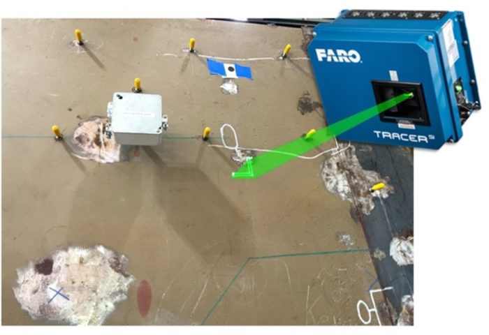
FARO Tracer SI projecting a new component onto an existing concrete wall
point3D recently introduced the FARO Tracer SI to its cutting-edge hardware technology line-up. This high-accuracy layout projector is a first-of-its-kind advanced laser imager that can optimize many existing shipbuilding processes. In addition, its user interface is simple and, once set up, can be put in a registered state with minimal effort.
The FARO Tracer SI accurately projects CAD-based laser images onto any surface allowing operators to outline parts, artifacts, or areas of interest. Assembled or placed components can be scanned to ensure conformance and proper positioning, detecting real-time errors. As a result, non-conforming parts and assemblies are identified and fixed immediately, saving manufacturers expensive rework costs.
point3D tested the FARO Tracer SI in a simulation mock-up of a simple ship compartment being used for multiple training applications. We first scanned the compartment with a FARO Focus 3D Lidar Scanner, then imported the data into Bloom Cloud Engine for registration and alignment. Next, we exported the .RCP (Autodesk Recap) file into Autodesk 3D Studio Max, enabling us to draw splines onto the point cloud. The splines were then exported along with the mesh into FARO BuildIT.1
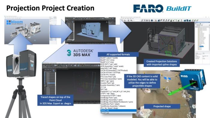
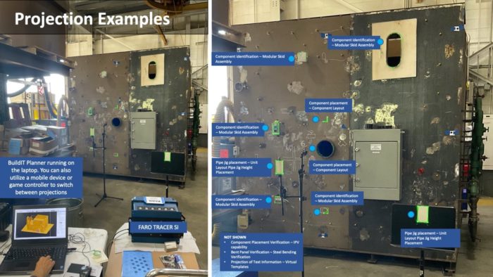
Once in FARO BuildIT Planner, alignment points could be established and the imported outlines defined. Next, elements are created using IPV, which will scan the aligned part and provide photographic verification of installation accuracy compared to the originally projected item. Our demonstration involved several sample elements representative of potential shipbuilding use cases, including:
Component placement and layout verification (IPV)
Projection assists with the layout of mounting studs, electrical components, pipe runs, and numerous other assemblies.
Unit layout pipe jig height placement
Ship units are placed on pipe jigs; if the unit has any curvature, the height of the pipe jigs needs to be adjusted to support the bend in the shell structure. Using the FARO Tracer SI, you can project the specific measurements and align them with a fixed target and minimal effort.
Virtual templating / Text projection
You can project critical template or stencil information onto a flat or curved surface to enable marking for ship names and numbers.
Modular Skid Assembly
Proportions of the ship are often built in a fixed station as a module. This module can then be built-out using projection aligned to the skid/raft.
Steel bending verification
Based on the provided loft or structure sketches, the existing cold steel bending process utilizes the Nieland 1000T press to shape and bend the plates into the desired form manually. The bend lines are lofted onto the plates via the drawing and traditional measurement methods and then used as the reference lines for the bending machine. The plate itself is often removed from the machine to do a verification check with the plywood offsets. The FARO Tracer SI is then utilized to project the bend lines onto the panel to guide the cold bending process.
The FARO Tracer SI is an extremely cost-effective solution. At an average initial investment of $50,0002, manufacturers will benefit from its ability to save on rework expenses, change orders, schedule delays, and dispute costs.
Additional features of the FARO Tracer SI include:
- Positional Accuracy: 0.25mm @ 5m (0.010 in @ 16.4 ft)
- Range of Projection and IPV: 1.8 to 15.2 m (6 to 50 ft)
- Capability to simultaneously project multiple images at once
- Control multiple Tracer SI projectors from a single computer
- Uses a green laser to be visible in high lumens locations
- Easily transported with a total weight of 38 lbs
Going beyond virtual templating and positioning, the FARO Tracer SI enables targetless, feature-based alignment and In-Process verification (IVP). Its high-contrast imaging, accurate and repeatable projection and powerful, easy-to-use software make this tool a new industry standard for repeatable laser-guided assembly.
To learn more about the FARO Tracer SI laser projection and how it can be utilized in shipbuilding, please contact the point3D sales team at sales@point3D.com
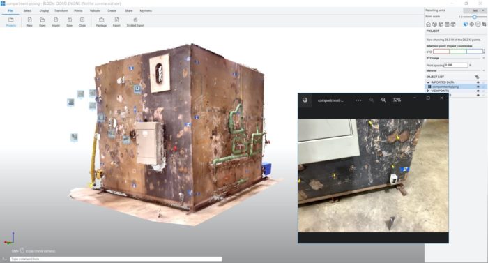
FARO Data registered in BloomCE software
1 BuildIT does not allow edge extraction from a 3D model when inserting a mesh.
2 Estimated cost includes the FARO Tracer SI and Tracer Rolling Stand. Operator and Planner software solutions along with two days of training.
Additional information and links:
FARO Tracer SI Video | FARO Tracer SI Technical Specifications | Article: How Laser Projectors Work
Tags: Fabrication, FARO, manufacturing, project_planning, qualitycontrol, Scanning
Categorized in: Articles
This post was written by Gregory Lawes